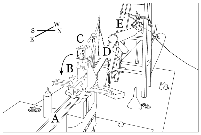
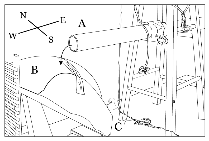
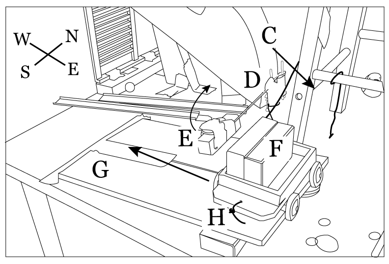
The Rube Goldberg Wedding Machine
Lots of Blah Blah Text
I can't just not give all the details of how this came to be. But that doesn't mean others have to read it. There's always the option to jump directly to the diagrams or jump directly to the video.Background
Friends (Ruth and Benj) got married Saturday May 11, 2013, and on Sunday, May 12, 2013, they had a post-wedding celebration, a.k.a. Sunday Funday, a.k.a. Ruth's birthday. They had a big tent set up in their back yard, with lots of food and stuff. They also had a group activity. They formed 5 groups from the willing participants, provided each group with an area to work (2 tables), a box of various objects, and access to general purpose things (wood, cardboard, tools, pipes, duct and electricians tape, and lots more).
The Challenge
Each group was challenged to build a Rube Goldberg style machine given the available supplies. Each machine would trigger the next one in sequence. And the final machine would trigger a trebuchet that they provided that would fling cake (well, a cup cake) at the bridge and groom, about 20 feet away. We had about 2 hours to work on it, while chatting and socializing. At some point, they also suggested that we should talk to the neighboring groups, to make sure one machine could trigger the next one.
Our Group
There were a handful of people in our group, including several engineers plus a carpenter/contractor, who could actually translate theory into practice. There were also a few kids (~10 years old) who were interested in helping and were able to make important pieces of the machine. Also, everyone got along. There were no egos or assholes, and that seemed to be the case with all of the groups. Perhaps that reflects on the type of people Ruth and Benj like. Also, since it was a cooperative activity, we weren't competing with the other teams. Sometimes someone from another group would ask us if we needed some parts, and almost every time it was something we didn't need and were happy to give to them.
The Creative Process
Having seen things like the OK Go video "This Too Shall Pass" and similarly complex Rube Goldberg machines, I assumed that the way it worked as that a bunch of engineers got together with some draft paper, slide rules, computers, and a book of equations. But the way it worked was quite different.
It really was an "organic" "bottom up" process. Or in other words "total chaos, experiments, and duct tape," but it turned out well. It could be summarized as follows:
- Examine objects to come up with an idea how they can be used
- Design a way for them to perform their function
- Figure out how the object can connect to the other parts of the machine
- Design a way to trigger it and to prevent it accidentally self-triggering
Here are a few examples.
- The scale: There was a balance scale in our box. We thought it'd be cool to use it so it would tip and do something. To do that we could either have something pour into one side of the scale, or have something pin down the lighter side. We had a lot of pennies and a funnel. We thought the pennies could pour into one tray, making a delightful clattering noise and eventually shift the weight. However the logistics getting the pennies to pour were complicated enough that we put it on the back burner. We didn't even consider what the moving balance would do next. The balance can be seen, unused, in some of the figures. There wee many pennies scattered on the table, but they are not shown in the figures.
- The metal chain: Another object we had was a metal chain. Attached to the end of it was a magnet. We thought it would be cool to use it as a sort of pendulum. Have the chain swing the magnet, contact something at one end of its motion and then pull it out as it swung back. It could either pull a release tab on something or move something from one side of a gap to another. However, this presented several problems. The object would have to be light enough so that the magnet could "grab" it. If that was the case, it was unlikely it would be heavy enough so that it would escape the magnet when it got to the far side. So that meant it would have to trip a trigger. Also, positioning the chain so it would fall with enough force would be difficult. While there was a lot of spare wood, the only tall enough pre-built structures we had ready access to were the stools and we were using them elsewhere. Also, securing the chain would probably require drilling a hole in something and screwing in some bolt. It was a cool object, but given the limited time, we decided against using it and it went back into the box.
- The hotwheels car launcher: As an example of something we did use, we found some hotwheels tracks, cars, and a few launchers, in our box. One launcher was spring loaded. Pressing the button and releases the spring and launches the car. We did some testing. Obviously, the car would be the thing that moves. We did a few tests and quickly determined it was NOT strong enough to make the car do a loop-de-loop, and in fact, to go uphill any amount, we needed to make sure the car was firmly against the launcher. The next thing we realized was that the launch button was very stiff and would require a significant amount of force to trigger it. That got us to thinking about having something heavy fall down on it. There's the question of what and then the question of how do we make it reliable. We had a large pipe and a small pipe, and put the small pipe inside the large pipe, and used the large pipe to guide the small pipe down onto the launch button. That worked, but not reliably, and didn't seem to let the spring transmit its full force to the car. So the next step was to tape the bottom of the small pipe and weight it down with sand and small rocks. That seemed to work decently. Then we needed a whole mounting infrastructure, for the launcher, the track, the two pipes, and their triggers. That started with a stool, but then continued with an egg carton and lots of wooden blocks to form a floor. Plus duct tape, lots of duct tape.
- The cart: A final example of something we used was the cart
with wheels. We didn't really know how things would connect together
within our own machine. An hour into the process, Ruth suggested the
different groups talk to each other to work out how one machine would
trigger the next. We talked to the next group whose table was perpendicular
to ours. The first thing we found out was that the start of their
machine was at the far end of their table, which mean connecting
the two machines would be a bit more complicated.
We decided we'd run a string from the end of our machine to the start of theirs, perhaps going through some pulleys or something. But that meant we needed to provide a good bit of force. We figured that sending a cart rolling off the edge of our table with a string tied to it would do the trick. Gravity would keep it going down and pull for 2 feet or so as it fell. And just to make sure it would go, we put some wooden blocks in the cart for weight—yes, I know that doesn't make it fall faster, but it tends to make it less prone to get stuck, and it gives more momentum to the tug on the string.
The next question was how to we get the cart to roll off the table. Fairly quickly we decided that we'd set up a little ramp and have it roll off of that. Then we figured the golf ball coming out of the tube and funnel could be used as a trigger for the cart. And then, after playing around a bit, we realized we needed a reliable way to stop the cart from rolling down the ramp the rest of the time. We needed to put in something simple to chock the wheels (or at least one wheel). We also needed a way to remove the chocks and have it so the cart rolled straight off the table, as opposed to turning 90° and hitting the side of the funnel. We did some experience with some extra hotwheels tracks, which was good for channeling the cart, but bad for friction. There was nothing we found that we could put on the track that would effectively stop the cart from moving. So we ditched the tracks (or rather, we left them between the ramp and the funnel, visible in the last figure). Playing with a wooden block on the wooden ramp, we discovered we could effectively stop the cart from going. But then how to do we remove the chock?
We had a long metal rod and attached the chock to one end of the rod, and attached the other end to a sort of gate, fashioned from a bunch of colorful tongue depressors fastened together by black electrician's tape (all our duct tape had been used by that point). So the golf ball would hit the gate and because of the long lever-arm, it would knock away the chocks. In theory.
In practice, the ball would come out of the tube, hit the ramp and then bounce over the gate and skitter off the table. A few adjustments to the ramp and the funnel (and some tape on the top) effectively damped the energy of the golf ball and allowed it to hit the gate, move the chock and send it on its way. And speaking of no triggering something, the figure shows the cart rotated 90° from its normal position. That was before we had everything secured. Since at that point the string on the cart was connected (loosely) to the next machine, we didn't want to accidentally trigger them, so we had the cart sitting so its wheels where hanging off the edge of the top of the ramp, preventing it from moving. I didn't have any reference pictures of everything ready to go so I just used the one I had.
Connecting the Machines
As it turns out, ours was to be the first machine, so no one had to trigger us. Triggering the next group was a bit tricky, but once we got the cart working, we were able to make our machine generate a good tug on a string that went through the tent through a few pulleys and into the next team's machine.
Lessons of Physics
"Gravity is a harsh mistress." -- The Tick.
The cool thing about these machines is they provide a visceral demonstration of basic physics. Potential and kinetic energy. Friction. Moment-arms and momentum. Force over area and distance. And of course the "simple machines" like the lever, wheel and axle, pulley, and inclined plane.
Below is a design for the Rube Goldberg Wedding Machine, as presented and described in Figures 1 - 6 (patent not pending).
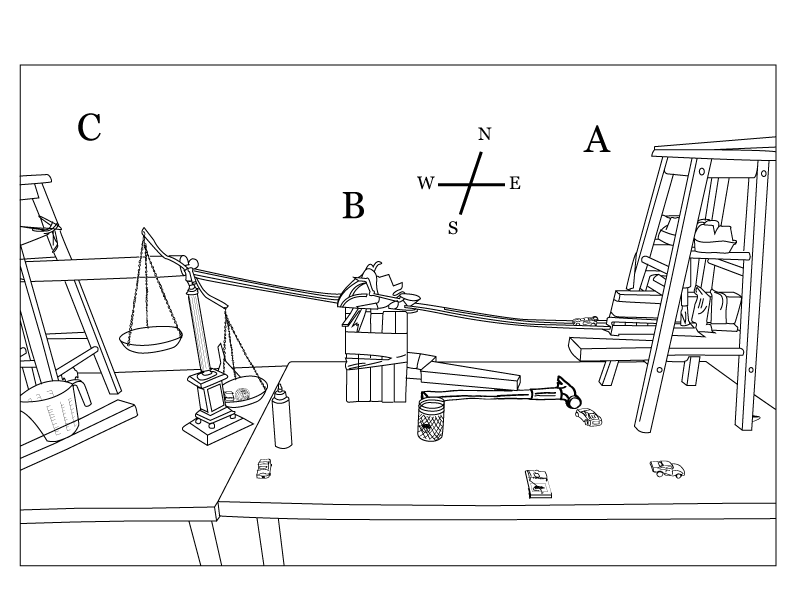
Figure 1: First Components of the Wedding Machine
Machine #1 of the basic Wedding Machine (Series 4700) serves as the front-end to a series of 5 machines, custom designed to assist with wedding necessities, viz: fair distribution of nuptial cake to bride and groom. We describe the operation of WM-S4700 Machine #1 below.
Figure 1 shows the basic system, which comprises 3 components, labeled A, B, and C in the figure. Roughly speaking, Component A comprises the stool, its supporting mechanisms, and connecting track; Component B comprises the central support structure, the incoming and outgoing track, and car exchange mechanism; Component C comprises the second stool, its support mechanisms, large tube, funnel, ramp, cart, and remainder of the machine. Any tools, spare parts, or additional components that appear in the diagrams but are not described are not intrinsic to the operation of the machine and are included for field maintenance, redundancy, or aesthetic reasons.
Each subsystem is described below.
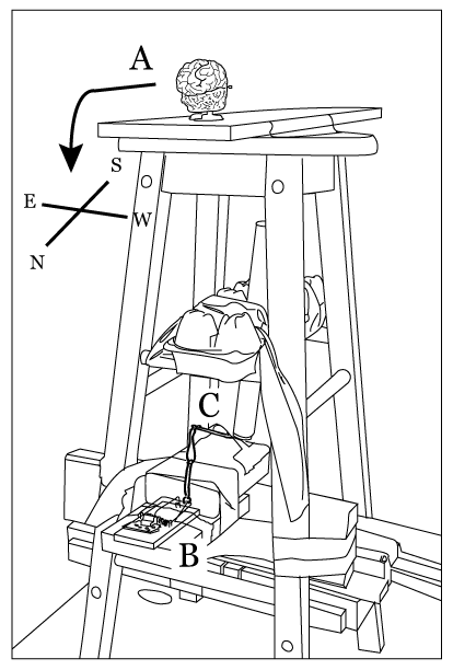
Figure 2: Component "A": Backside View
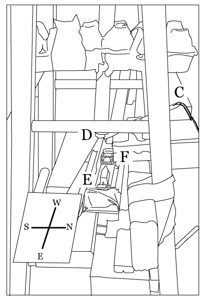
Figure 3: Component "A": Left View
